
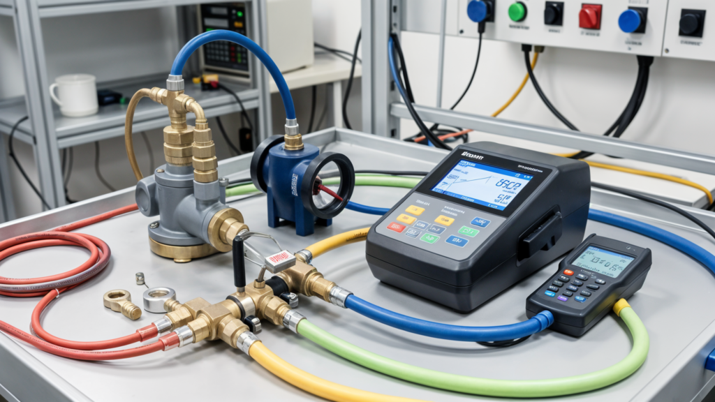
Pressure transmitter calibration is a critical process for verifying that smart and analog transmitters report pressure accurately across their working range. This practical guide compares both methods, including five-point testing, HART trims, loop-current checks, reference accuracy, and documentation.
Pressure Transmitter Calibration for Analog Devices
An analog pressure transmitter converts pressure to a proportional 4–20 mA current: 4 mA at zero (lower range value) and 20 mA at span (upper range value), with the current proportional in between. Calibrating it means applying known pressures and comparing the loop current against the expected values at each point.
The classic procedure is a five-point test: apply 0, 25, 50, 75, and 100 percent of range, record the current at each point, then typically repeat coming back down to expose hysteresis. If the transmitter is out of tolerance, you adjust zero and span — traditionally with potentiometers on the electronics — and repeat the test until the errors fall within the required limits. Simple, robust, and fully understood by every instrumentation technician.
Pressure Transmitter Calibration for Smart HART Devices
Smart transmitters do the same sensing job but add digital communication. HART superimposes a digital FSK signal on the 4–20 mA loop, so the same two wires carry both the analog signal and digital data. Fieldbus devices communicate digitally only. With a communicator or calibration software you can:
- Read the process variable and the transmitter’s internal digital readings directly.
- Perform digital trims — zero trim at atmosphere or a reference pressure, and upper and lower sensor trims to correct the sensing element.
- Adjust range, damping, and units without touching the instrument.
- Access diagnostics and configuration records.
Calibrating a smart transmitter is a two-part job: the sensor must be correct (sensor trim), and the 4–20 mA output must be correct (output, or D-A, trim). Trimming the sensor with the communicator changes how the transmitter interprets pressure; verifying the current output confirms the loop side. Both matter.
Calibration Procedure: Smart vs Analog
The reference pressure part of the job is identical. You need a pressure reference — a deadweight tester for the highest accuracy, or a digital pressure calibrator with the right range — plus a way to measure the output. From there the procedures diverge:
- Analog: apply each test pressure, read the loop current with the calibrator, and compare against the expected value for that point. Adjust zero and span mechanically if needed. Record manually.
- Smart (HART): connect the communicator or communicating calibrator, apply each test pressure, and read both the digital process variable and the loop current. If the sensor is off, perform a zero or upper sensor trim; if the output is off after trimming, perform a D-A trim. The communicator records the before-and-after state, and a documenting calibrator logs as-found and as-left results automatically.
In both cases, the test points should cover the full range, including the 4 mA and 20 mA endpoints, and the comparison should be made against a reference several times more accurate than the transmitter being tested.
A Typical Smart Transmitter Calibration, Step by Step
- Record the transmitter tag, range, and current configuration from the communicator before you start.
- Isolate and depressurize the process safely, then connect the pressure reference and the calibrator to the loop.
- Apply the zero reference (atmosphere or a known reference pressure) and perform a zero trim if the process variable deviates.
- Apply 0, 25, 50, 75, and 100 percent of range, recording the transmitter’s output — digital process variable and loop current — at each point.
- Repeat in descending order to expose hysteresis and repeatability errors.
- If output errors exceed limits, verify the sensor first (sensor trim), then correct the current output (D-A trim) if the loop side is off.
- Restore the configuration and range to the documented values, complete the as-left test, and record the results.
The same steps apply to analog transmitters minus the communicator: adjustments are made on the electronics, and results are recorded by hand or in software.
Smart vs Analog: Practical Differences
- Adjustment quality. Digital trims are precise and repeatable; analog pots are coarser and can interact (adjusting span can shift zero).
- Diagnostics. Smart transmitters report drift, sensor problems, and loop conditions; analog transmitters give you nothing beyond the signal.
- Configuration. Smart units can be re-ranged and re-configured remotely, which also means configuration can be corrupted — configuration management becomes part of the job.
- Simplicity. Analog transmitters have fewer failure modes and no configuration to manage; many plants keep them for exactly that reason.
- Skill set. Technicians need both: analog skills for legacy instruments, communicator skills for smart ones. Most plants run a mix, and the calibration program must cover both.
Common Calibration Mistakes to Avoid
- Trimming the output (D-A) when the sensor is the problem — check the process variable before touching the current loop.
- Using a reference with insufficient accuracy for the device under test — the comparison is meaningless if the reference error is a big fraction of the tolerance.
- Skipping mid-point checks — a transmitter can be perfect at zero and span and nonlinear in between.
- Forgetting to restore configuration after a trim — range and damping changes left in place cause the next job to fail.
Calibration Intervals and Documentation
Most plants calibrate pressure transmitters every 6 to 12 months, but the right interval depends on criticality, environment, and drift history — treat it as a starting point and adjust with data. Whatever the interval, document as-found and as-left results, the reference used, and its traceability. That record is what makes a calibration defensible.
Beyond the interval, define the test in the procedure: which points, how many up-down runs, the tolerance (often 0.1 percent of span or tighter for critical service), and the acceptable as-left criteria. A written procedure makes results repeatable between technicians and gives auditors the context they need to judge the record.
Pressure Transmitter Calibration: Trusted Manufacturer Resources
For pressure transmitter calibration, compare the procedure and instrument capabilities with official manufacturer guidance before applying a trim or accepting a result:
- Fluke HART pressure transmitter calibration guide explains smart trims and documenting calibration workflows.
- Fluke maintenance guidance for HART pressure transmitters covers testing and adjustment considerations.
- FieldComm Group HART resources provide protocol and device interoperability context.
- Additel pressure calibrators provide manufacturer information for pressure reference alternatives.
Always confirm the exact transmitter model, range, accuracy, approved trim procedure, and safety requirements in the manufacturer documentation and site procedure.
Equipment for Pressure Transmitter Calibration
- Pressure calibrators — field references with integrated pumps and mA measurement.
- Deadweight testers — primary references for high-accuracy and lab work.
- Pressure modules — range flexibility for one calibrator.
- HART communicators — digital access to smart transmitters.
- Loop calibrators — mA source and measurement for output checks.
- Process instruments — the transmitters and related hardware.
Choosing the reference is straightforward: match the accuracy to the application. A 0.05 percent digital calibrator covers routine transmitter work; custody transfer and critical safety instruments deserve the best reference you can justify, and the comparison should always be documented with the reference’s certificate number.
Get Help Matching Your Calibration Setup
Whether your plant runs analog transmitters, a full fleet of smart HART instruments, or a mix, the reference and the workflow have to match the job. Tell us your transmitter types, pressure ranges, and accuracy requirements, and we will recommend the right calibrators, modules, and communicators. Request a quotation and we will respond with a setup that fits your instrument list.
Editorial note: This guide was prepared by the Indo Multimeter Editorial Team for engineers and technicians researching test, measurement, and calibration equipment. Specifications and application guidance should be checked against the manufacturer documentation and the requirements of your calibration procedure.